The activity, coordinated by
Prof. F. Posa of the University of Bari, concerns in situ installation of
calibrators and data acquisition.
All the measurements will be done in bands C and
X, both before and during the mission, in association with passage(s) over the Matera test
site, or according to the mission plan.
The corner reflectors used for this mission have
already been amply tried out in previous X-SAR/SIR-C missions.
In this activity, as in the previous one, the
effects of corner reflector surface curvature on their radar cross-section will be
considered.
The corner reflectors
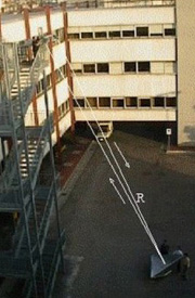
These are trihedral corner reflectors with 1.8 meter sides, whose
response to an incident signal is returned in its direction (a feature making them
treatable as point targets), and whose radar cross-section is equal to
 (Robertson, 1947).
This implies a response of approx. 36 dB for band C
and 41 dB for band X.
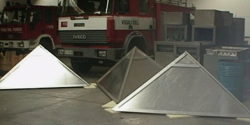
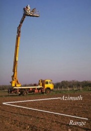
Corner Reflectors at the Centro
Polifunzionale della Protezione Civile

Positioning of a corner reflector on a fire
service vehicle
located at the Rondanini hospital, Rome
The ARCs
The devices known as ARCs (Active Radar Calibrators) are
electronic apparatuses able to receive the radar signal on the ground, amplify it and send
it back to the sensor. They consist of a receiving antenna, a radio-frequency amplifier
and a transmitting antenna. The signal reaching the receiving antenna is amplified and
sent back to the sensor, which records greater power than supplied by a simple reflector,
with an obvious increase in measured RCS.
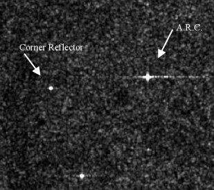 |
Image of a test site from a
microwave sensor, bringing out the different radar cross-section between an active and a
passive calibrator. |
Scatterometer in band C
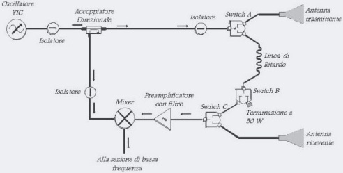
A scatterometer in band C has been designed, produced and
successfully tested, for in situ measurements of radar cross-sections (RCS). The
instrument, operating in FM-CW (Frequency Modulated - Continuous Wave) mode, transmits a
wave frequency-modulated in a 300 MHz interval around a central frequency of 5.3 GHz. This
frequency modulation allows the signals back-diffused from various scatterers inside the
antenna footprint to be resolved. The instrument is able to measure RCSs between +10 and
-40 dB, for targets at distances of between 7 and 100 m. The acquisition parameters can be
controlled from a PC through a graphic interface.
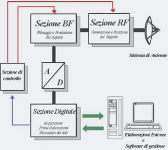
Microwave and low-frequency sections of the
scatterometer in band C
 |
Measurements with the
scatterometer in band C |
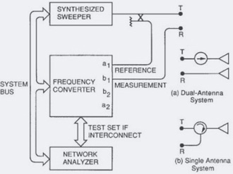
| Block diagram of the scatterometer in band C |
|
Vectorial Network Analyzer as
scatterometer in bands C and X
A Vectorial Network Analyzer can be used as a
polarimetric multifrequency microwave scatterometer.
This instrument operates in a broad frequency range (from 0.04 to 13.5 GHz) with a
frequency resolution of 1 KHz, and has a wide dynamic range (from 70 to 98 dB, varying
with the frequency). The experimental setup includes, as well as the Analyzer, a system of
antennas (rectangular horns) operating in bands C and X, with the possibility of selecting
the linear polarization states before each data-gathering run. This system enables
characterization of the complex frequency response of any network under test, by measuring
the scattering parameters and the relation obtaining between them and the scattering
matrix.
 Configuration of Analyzer for
scatterometric measurements
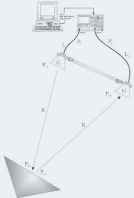
Diagram of experimental setup |
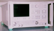 The Vectorial Network
Analyzer: Wiltron 377225B
Measurements with the Analyzer in C and X bands |
|