Description of configuration of radars
mounted on board the Shuttle
Simple presentation
The SRTM mission will be carried out using
the US Shuttle Transportation System (STS) as space vehicle, with the on-board
instrumentation (Synthetic Aperture Radars) coming from the previous SIR-C/X-SAR missions.
This instrumentation has been modified in order to attain the specific objectives of this
mission.
Inside the American STS (Shuttle Transportation System) two radars,
complete with antennas, will be operating. The first, supplied by NASA/Jet Propulsion
Laboratory, is in band C (5.3 GHz), and the second, supplied by the Italian and German
Space Agencies, in band X (9.6 GHz).
Both radars will be controlled from the ground through a command and
control system resident at NASA's Johnson Space Center operations center in Houston.
For this mission, NASA/JPL have developed a special highly
sophisticated structural and mechanical system enabling a mechanical arm, carrying two
other antennas at its end, to be extended to a length of sixty meters. These antennas at
the end of the arm will enable reception of the echo from the radars located on board the
STS. This system of two antennas per frequency band will enable the third dimension to be
reconstructed and topographical output to be obtained in both bands (C and X). A further
highly sophisticated system, known as AODA, has been designed to control deployment of the
mechanical arm, verify alignment of the antennas and supply all data needed for
end-of-mission processing of the data recorded during the mission aboard the Shuttle.
Technical presentation
The SRTM flight segment consists of four major subsystems;
the Structural and Mechanical System (SMS), the C-band (5.3 GHz) Aperture Radar (C-Radar)
system, the Attitude and Orbit Determination Avionics (AODA) system, and the X-band (9.6
GHz) Radar (X-Radar) system. Of the above systems, the SMS, C-Radar, and X-Radar use
existing SIR-C/X-SAR hardware with modification and augmentation, whereas the AODA is a
new system. Refer to Figures 1-2 and 1-3 for an overview of the SRTM experiments.
SIR-C, which was developed by the Jet Propulsion
Laboratory (JPL), is comprised of two active aperture phased array radar systems that can
operate in the L-band and C-band (the L-band capability will nominally not be used). The
antenna panels are supported by a 4 x 12 meter rigid structure that attaches to the
orbiter at four sill trunnions and two keel trunnions. Pallet-mounted electronic
assemblies provide RF excitation, command, timing, and data handling functions. The C-band
(and L-band) radar operates with vertical and horizontal polarization. C-Radar uses the
C-band part of the SIR-C hardware with addition of a new Outboard Antenna Subassembly
(OAS) to provide a 60-meter baseline interferometric receive capability, as well as other
hardware to be outlined in Section 2 of this manual. The C-Radar inboard antenna beams can
be electronically steered to any angle between 20o and 60o
off-nadir, while the outboard can be electronically steered plus and minus TBSo.
C-Radar data will be stored on high rate digital cassette recorders.
The X-SAR system was developed as a joint effort by the
German space agency (DARA) and the Italian space agency (Agenzia Spaziale Italiana, ASI),
and is a conventional SAR that uses a vertically polarized slotted waveguide antenna.
Pallet-mounted electronics provide RF excitation, command, timing, and data handling
functions. X-Radar is comprised of the basic X-SAR flight equipment and an additional
(receive only) antenna (mounted in a fixed position at the end of the mast) with
associated electronics. The X-Radar inboard antenna will be mechanically tilted in
elevation (tilt range of 15o to 60o) from its launch stowed position
to the same point angle as that of the X-band outboard antenna. Once the inboard beam has
been positioned, it will nominally remain at the same angle throughout the mission. Beam
alignment will subsequently be accomplished through electronic steering of the outboard
antenna beam. X-Radar data will be stored on high-rate cassette recorders.
The AODA will provide mast deployment verification and
antenna alignment verification, as well as provide the data necessary to reconstruct the
SRTM interferometric baseline vector and antenna attitudes and orbital positions. It will
also provide limited attitude control of the Outboard Antenna Structure (OAS). AODA is
comprised of several systems, including star and target tracker assemblies, electronic
distance meters, inertial reference units, and global positioning systems.
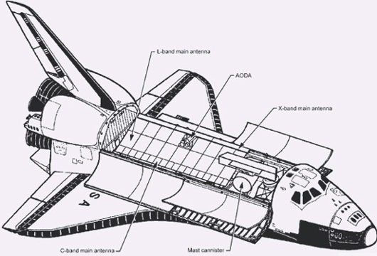
Figure 1
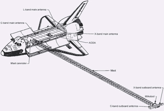
Figure 2
Figures 1 and 2 show the STS configuration
with arm not yet deployed (fig. 1), and at maximum extension during the operational phase
of the mission (fig. 2).
|