Background
on radars
The initial development of radar
imaging principles can be traced to Carl Wiley of Goodyear Aircraft Corporation in June of
1951. The first airborne radar images were made by a group at the University of Illinois
on July 8, 1953. Subsequent research by Goodyear Corporation and the University of
Michigan significantly improved the resolution of side-looking airborne radar images. The
new radar imaging technology was initially recognized for its military applications and
was classified until 1964. The first non-military radar mapping project was accomplished
in 1968 by the Westinghouse Electric Corporation and Raytheon. The Central American
province of Darien was completely imaged, which was previously impossible due to constant
cloud cover.
Typical RADAR (RAdio Detection and Ranging) measures the
strength and round-trip time of microwave signals reflected off a distant surface or
object. The radar antenna alternately transmits and receives pulses at particular
microwave wavelengths (in the range 1 cm to 1 m, which corresponds to a frequency range of
about 300 MHz to 30 GHz) and polarizations (waves polarized in a single vertical or
horizontal plane). For an imaging radar system, about 1500 highpower pulses per second are
transmitted toward the target or imaging area, with each pulse having a pulse duration
(pulse width) of typically 10-50 microseconds (m s). The pulse normally covers a small
band of frequencies, centered on the frequency selected for the radar. (Typical bandwidths
for an imaging radar are in the range 10 to 200 MHz). At the Earth's surface, the energy
in the radar pulse is scattered in all directions, with some reflected back toward the
antenna. This backscatter returns to the radar as a weaker radar echo and is received by
the antenna in a specific polarization (horizontal or vertical, not necessarily the same
as the transmitted pulse). These echoes are then converted to digital data and passed to a
data recorder for later processing and display as an image. Given that the radar pulse
travels at the speed of light, the measured time for the round-trip of a particular pulse
can be used to calculate the distance or range to the reflecting object. The chosen pulse
bandwidth determines the resolution in the range (cross-track) direction. Higher bandwidth
means finer resolution in this dimension.
In the case of imaging radar, the radar moves along a
flight path and the area illuminated by the radar, or footprint, is moved along the
surface in a swath, building the image as it does so. The length of the radar antenna
determines the resolution in the azimuth (along-track) direction of the image (the longer
the antenna, the finer the resolution in this dimension). Synthetic Aperture Radar (SAR)
refers to a technique used to synthesize a very long antenna by combining signals (echoes)
received by the radar antenna as it moves along its flight path. Aperture is the area used
to collect the reflected energy; i.e., the antenna. A synthetic aperture is constructed by
moving a real aperture, or antenna, through a series of positions along a given flight
path. As the radar moves, a pulse is transmitted at each position; the return echoes are
then recorded. Because the radar is moving relative to the ground, the returned echoes are
Doppler-shifted (negatively as the radar approaches a target; positively as it moves
away). Comparing the Doppler-shifted frequencies to a reference frequency allows many
returned signals to be "focused" on a single point, effectively increasing the
length of the antenna that is imaging that particular point. This focusing operation is
commonly known as SAR processing.
 |
 |
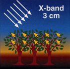 |
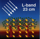
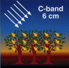
| Primary interaction of L, C and X band
microwaves with forest canopies. |
|